Key Takeaway: RS485 is the industrial wiring standard that lets microcontrollers talk reliably over long distances in noisy factory environments, and Modbus RTU is the simple master-slave protocol that runs on top of it — together they let an Arduino or STM32 read sensors, drive VFDs, and talk to HMIs using just two wires.
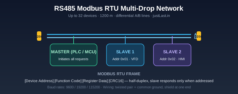
Table of Contents
1. Why RS485 and Modbus Dominate Industrial Wiring
Walk through any factory and you will find VFDs, HMIs, PLCs, energy meters, and sensors connected with a simple twisted pair of wires. That wiring is almost certainly RS485, and the messages flowing over it are almost certainly Modbus RTU. The pairing has been the backbone of industrial automation for forty years, and it remains the cheapest, most reliable way to connect devices over distances where I2C and UART give up.
For a small workshop or an automation integrator, understanding RS485 Modbus Arduino setups unlocks a huge library of cheap industrial hardware: Modbus temperature controllers, VFDs, energy meters, and relay modules that cost a fraction of their PLC equivalents. You can read and control all of them from an Arduino or STM32. This guide covers the electrical layer, the protocol, the wiring rules, and working code for both master and slave.
2. How RS485 Physically Works
RS485 is a differential serial standard. Instead of sending a signal on a single wire referenced to ground, it sends the same signal on two wires — labelled A and B — as a voltage difference. The receiver only looks at the difference between the two lines, so any noise that affects both wires equally cancels out. That is why RS485 can run 1,200 metres and shrug off the interference from motors, contactors, and VFDs that would destroy a normal UART signal.
The key electrical facts: RS485 is half-duplex in its most common form (devices share the same two wires, so only one talks at a time), it supports up to 32 unit loads on a single bus (roughly 32 devices), and the bus must be terminated with 120 ohm resistors at both ends to prevent reflections. A common ground between devices is also required, and the shield should be earthed at one end only.
Compare this with the I2C and SPI buses we have covered in our STM32 I2C masterclass — those are board-level buses designed for centimetres, not metres. RS485 is the distance-and-noise answer, which is exactly why industry standardised on it.
3. Modbus RTU Protocol Basics
Modbus RTU is a request-response protocol with one master and many slaves. Each slave has an address from 1 to 247; the master sends a frame addressed to one slave, and that slave alone replies. A Modbus frame is compact:
[Slave Address] [Function Code] [Data...] [CRC16]The most common function codes are:
- 01 (0x01) — read coils (digital outputs)
- 02 (0x02) — read discrete inputs
- 03 (0x03) — read holding registers (16-bit values, the workhorse of Modbus)
- 04 (0x04) — read input registers
- 05 (0x05) — write a single coil
- 06 (0x06) — write a single holding register
- 16 (0x10) — write multiple holding registers
Holding registers are 16-bit words, and each device’s data sheet lists its register map — for example, a VFD might expose “run command” at register 0x2000 and “current frequency” at register 0x2001. Reading and writing those registers is how you control the device. The CRC16 at the end lets the receiver detect corrupted frames, which is essential on a noisy factory floor.
4. Hardware: MAX485 Adapters and Wiring
Microcontrollers do not speak RS485 natively — they output single-ended UART levels. The standard solution is a MAX485 transceiver chip or a ready-made MAX485 TTL-to-RS485 adapter module, which costs only a few hundred rupees in India. The module exposes four pins to the microcontroller: VCC, GND, DI (data in), and RO (receiver out), plus DE and RE which together enable the transmitter.
For a two-wire half-duplex bus you must switch between transmit and receive. On many adapters, DE and RE are already tied together, so one control pin on the microcontroller (often called the direction pin) switches the module between sending and listening. Put the direction pin HIGH before sending a frame and LOW immediately after.
To the outside world the module presents the A and B screw terminals, which connect to the twisted pair bus. This is the same transceiver topology used in industrial gateways — for a full system picture, see our ESP32 Modbus-to-MQTT gateway build.
5. RS485 Modbus with Arduino: Code
The easiest way to run a Modbus RTU master on Arduino is the ModbusMaster library. Here is a complete example that reads four holding registers from a slave at address 1 on every loop:
#include <ModbusMaster.h>

#define MAX485_DE 8   // direction enable pin
#define MAX485_RE 7   // receiver enable pin (often tied to DE)

ModbusMaster node;

void preTransmission() {
  digitalWrite(MAX485_RE, 1);
  digitalWrite(MAX485_DE, 1);
}
void postTransmission() {
  digitalWrite(MAX485_RE, 0);
  digitalWrite(MAX485_DE, 0);
}

void setup() {
  pinMode(MAX485_DE, OUTPUT);
  pinMode(MAX485_RE, OUTPUT);
  Serial.begin(9600);
  node.begin(1, Serial);          // slave address 1 on Serial (pins 0/1)
  node.preTransmission(preTransmission);
  node.postTransmission(postTransmission);
}

void loop() {
  uint8_t result = node.readHoldingRegisters(0x2000, 4);
  if (result == node.ku8MBSuccess) {
    for (uint8_t i = 0; i < 4; i++) {
      Serial.print("R"); Serial.print(0x2000 + i);
      Serial.print(" = "); Serial.println(node.getResponseBuffer(i));
    }
  } else {
    Serial.print("Modbus error: 0x");
    Serial.println(result, HEX);
  }
  delay(1000);
}
The preTransmission and postTransmission callbacks toggle the direction pin automatically, so the library handles the half-duplex switching. Set the same baud rate on the slave, wire A-A and B-B across the bus, and this sketch will read live register data from any Modbus RTU device. If you also need to publish that data to a dashboard, the architecture in our MQTT remote monitoring guide shows how to connect Modbus data to the internet.
6. Implementing a Slave on STM32
On an STM32 you can implement either a master or a slave. A slave is useful when you want a PLC or HMI to read sensor values from your custom board. Use a USART in asynchronous mode, an RS485 transceiver with the direction pin controlled by a GPIO, and a Modbus slave library or a simple state machine that parses frames and replies.
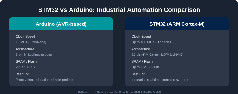
The STM32’s hardware UART makes framing easy: use the idle-line detection or a byte-timeout interrupt to know when a frame has ended, verify the CRC16, execute the requested read or write against your register array, and build the response frame. With the 72 MHz core you can service a slave at 115200 baud while still running a control loop — the same multi-tasking advantage discussed in our STM32 PID control guide.
One practical tip for STM32 slaves: keep the register map in a plain uint16_t array so function codes 03, 04, 06, and 16 all read and write the same memory. This makes the firmware trivial to extend — add a sensor, map it to a register, and the HMI immediately sees it.
7. Wiring Rules That Prevent Field Failures
Ninety percent of RS485 problems are wiring problems. Follow these rules and your bus will be rock solid:
- Use twisted-pair cable; the twist rejects interference.
- Connect A to A and B to B — reversing them is the #1 wiring mistake.
- Install a 120 ohm termination resistor at each physical end of the bus, not in the middle.
- Run a common ground wire between all devices; isolated transceivers help in large systems.
- Earth the shield at exactly one end.
- Keep the total cable length within 1,200 metres and the number of devices within the transceiver’s drive capacity (32 for standard transceivers).
- Use the lowest baud rate that meets your needs — 9,600 baud is far more robust than 115,200 on long runs.
These rules apply whether the master is a PLC, an ESP32, or an Arduino. They are also the reason industrial gateways physically isolate the RS485 side from the microcontroller side, as shown in our Modbus to MQTT gateway article.
Frequently Asked Questions
What is the difference between RS485 and Modbus?
RS485 is the electrical standard that defines the physical wiring and signalling (differential voltage on two wires). Modbus is the protocol — the message format and rules — that runs on top of RS485. Modbus can also run over RS232, TCP/IP, and USB; RS485 is just its most common transport.
Can an Arduino communicate over Modbus RS485?
Yes. Add a MAX485 TTL-to-RS485 adapter, use the ModbusMaster library for a master or a Modbus slave library for a slave, and control the direction pin in pre/post transmission callbacks. Wiring and baud rate must match the slave device.
How many devices can I connect on one RS485 bus?
Standard RS485 transceivers drive 32 unit loads, which is typically 32 devices. With lower-load transceivers (e.g., quarter-unit-load types) you can reach 128 devices. Modbus itself supports addresses 1 to 247.
Do I need termination resistors on RS485?
Yes, for runs longer than a few metres. Install a 120 ohm resistor across A-B at each physical end of the bus to prevent signal reflections that cause data corruption. Termination is less critical on very short test benches but always recommended.
What is a Modbus holding register?
A holding register is a 16-bit (two-byte) value that a Modbus slave stores and that a master can read (function 03) or write (function 06/16). Device manuals publish register maps that define what each address controls or reports.
Related Reading
- ESP32 Industrial IoT Gateway: Building a Modbus to MQTT Bridge
- MQTT-Based Remote Monitoring System for Industrial Machinery
- STM32 I2C Communication Masterclass
- PID Motor Control with Arduino and STM32
Sources
- Modbus Organization — Modbus Protocol Specifications
- Wikipedia — RS-485
- Simply Modbus — Protocol FAQ and Tutorials
- Texas Instruments — RS-485 Design Guide
Disclosure: This post contains affiliate links. If you purchase through them, justLast.in may earn a small commission at no extra cost to you. Buy MAX485 RS485 modules and Modbus accessories on Amazon.in.