Servo Motor Selection for CNC Retrofit: Torque, Speed, and Inertia
Key Takeaway
Servo motor selection for a CNC retrofit is won or lost at the load calculation. The motor must produce the peak torque at the required speed with the reflected inertia inside the drive’s stable envelope, and every number in the selection can be checked on paper before a motor is ordered.
Figure 1: Servo drive sizing works backwards from the load through the motor, amplifier, and cable
Table of Contents
1. Load Torque at the Shaft
The first step in servo motor selection cnc retrofit is the load torque at the motor shaft, and nothing else matters until this number is right. Torque is force times radius, so for a ball screw drive the tangential force from the cutting process or the axis motion is divided by the screw lead to give motor torque, then multiplied by the drive efficiency. For a rack and pinion it is the force times the pinion radius.
Every axis has three torque components. The process force is the cutting force or the pressing force, and it exists only while the tool is engaged. The friction force is the ways, the seals, and the wipers, and it exists whenever the axis moves. The gravity force exists on vertical axes and on inclined axes, and it exists even when the axis is stationary.
On a vertical Z axis the gravity torque does not go away when the motor stops, so the brake or the counterbalance must hold it, and the motor must still size for the acceleration torque when the axis moves. Write each component down in Newton metres and add them. Do not guess the cutting force from the material name; measure it or compute it from the depth of cut, the feed rate, and the tool geometry.
Section summary. Servo motor selection cnc retrofit is decided here. The load torque at the shaft is the sum of process, friction, gravity, and acceleration torque, and every one of them must be checked before the motor is chosen.
2. Speed at the Shaft
The speed at the motor shaft is the process speed divided by the drive ratio. For a ball screw with a 10 mm lead moving at 15 m/min, the screw turns at 1500 rpm. For a rotary table geared down 10:1, the motor runs ten times faster than the table. Gear ratio divides the speed seen at the motor and multiplies the torque seen at the motor, so the motor selection and the gearbox choice are one decision, not two.
The motor speed-torque curve falls as speed rises, and the usable speed is where the motor still has enough torque for the load. A motor rated at 3000 rpm may only produce half its rated torque at 4000 rpm, so a fast axis needs a motor chosen at speed, not at the nameplate rating.
For a CNC retrofit on a 415 V three phase 50 Hz supply, the DC bus is about 587 V. The motor voltage constant in volts per krpm must keep the back EMF below the bus voltage at the maximum speed, or the drive runs out of voltage and the axis weakens exactly when it needs torque most.
Section summary. Speed at the shaft is set by the process and the gear ratio, and the motor must deliver the load torque at that speed on the available bus voltage.
3. Inertia Ratio and Stability
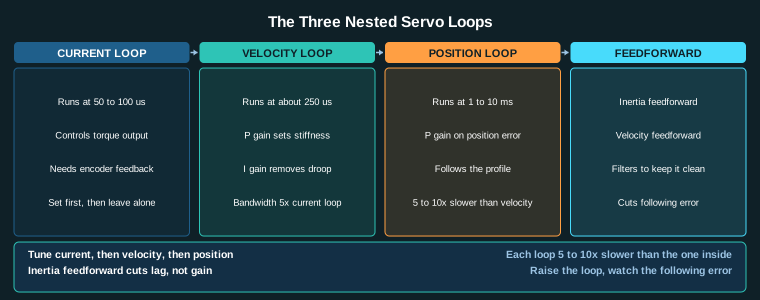
The inertia ratio is the load inertia reflected to the motor shaft divided by the motor rotor inertia. Reflection divides by the square of the gear ratio, so a 10:1 gearbox reduces reflected inertia by 100:1. This is the single most important number after torque, and it decides whether the axis can be tuned stably.
Keep the ratio below 10:1 for general purpose axes and below 5:1 for high acceleration axes. Above 10:1 the velocity loop has to be soft, the position loop has to be slow, and the axis hunts. Below 5:1 the loops can be stiff and the axis follows the command tightly. The ratio is not a preference; it is a stability limit.
If the ratio comes out high, re-gear to reduce reflected inertia, or choose a motor with larger rotor inertia, or both. Adding gear reduction is usually cheaper than buying a bigger motor, and it also reduces the motor speed requirement.
Section summary. Servo motor selection cnc retrofit fails on inertia ratio more often than on torque. Check the ratio before the torque, because a motor that has torque but no stability is a motor that will not commission.
4. RMS and Peak Duty
A motor has two ratings that matter: continuous torque at RMS duty, and peak torque for transients. RMS duty averages the torque over the duty cycle, so a motor that accelerates hard for one second and idles for nine seconds sizes on the average, not the peak. Peak torque sizes the deceleration, the crash stop, and the overload that the drive can survive for a few seconds.
For a CNC axis that cuts for twenty seconds and positions for ten, the duty cycle is 67 percent cutting and 33 percent positioning, and the RMS torque is the square root of the mean of the squared torques. Check the RMS torque against the continuous curve and the peak torque against the intermittent curve on the same motor datasheet.
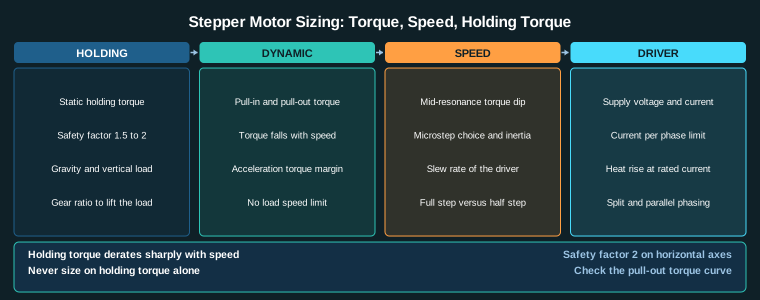
Do not size a servo on holding torque. That is a stepper specification. A servo is sized on the torque-speed curve at the operating speed, and the intermittent region is only for seconds, not minutes.
Section summary. RMS current decides the motor for duty cycle, peak current decides it for transients, and both must fit one motor curve.
5. The 415 V Supply and the DC Bus
A CNC retrofit in India runs on a 415 V three phase 50 Hz supply. After the three phase rectifier the DC bus is about 415 x sqrt(2) = 587 V, and the motor must work on that bus. The motor voltage constant in V/krpm sets the speed at which back EMF equals bus voltage, and above that speed the drive enters field weakening and loses torque.
Voltage fluctuation on the Indian grid can be plus or minus 10 percent or worse in an industrial estate, so the bus is not constant. A motor chosen at the edge of its voltage range will lose torque when the supply sags. Leave ten to fifteen percent headroom on the bus voltage so the axis keeps its torque when the voltage dips.
The regeneration problem is the other side of the bus. When a heavy axis decelerates, the motor acts as a generator and pushes energy back into the bus. The bus capacitor absorbs some of it, and a brake resistor absorbs the rest. Size the brake resistor for the worst case deceleration of the heaviest axis, or the bus over-voltage fault will trip the drive exactly when the machine stops.
Section summary. The motor voltage constant must match the 587 V bus with headroom, and the brake resistor must absorb the regeneration of the heaviest deceleration.
6. Ambient Temperature, Dust, and Enclosure
The Indian shop floor runs at 40 to 45 deg C ambient in summer, and a CNC enclosure traps motor heat. A motor rated for 40 deg C ambient will overheat at 50 deg C inside a cabinet, and the insulation life halves for every ten degrees above rating. Check the motor insulation class and the derating curve at the actual ambient.
Dust enters through the motor shaft seal and the fan, and it insulates the windings so the motor runs hotter than the datasheet says. Use an IP54 or IP65 motor on the machine side, and keep the drive in a separate cooled cabinet. The extra cost of a sealed motor is less than the cost of a rewind.
Voltage fluctuation and dust together are the reason Indian machine builders oversize by one frame. That oversizing is cheaper than a field failure, and it is a legitimate engineering decision when the supply and the environment are uncertain.
Section summary. Size the motor for 45 deg C ambient inside the enclosure, not for 25 deg C in a datasheet, and seal it against dust.
7. Cable and Drive Matching
The cable between the drive and the motor carries full motor current, and voltage drop on a long cable wastes torque. For a 10 A motor running 25 m on a 1.5 mm^2 copper cable, the loop resistance is about 1.1 ohm and the drop is about 11 V, which is real on a 587 V bus but more important at low speed where the motor voltage is small. Use shielded motor cable and keep it separate from VFD output cables.
The drive current rating must cover the motor peak current, not just the rated current. A 10 A motor with a 30 A peak needs a drive rated for 30 A, or the drive clips the current and the axis loses torque exactly when it needs it most.
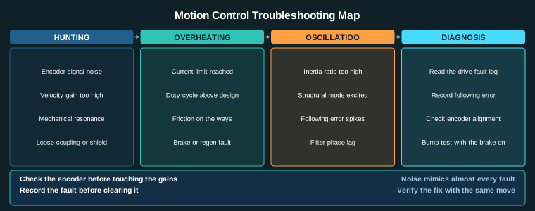
Encoder feedback cable is signal, not power, and it runs in its own trunking. A encoder cable run next to a VFD output picks up noise that looks like a position fault, and the symptom is an axis that hunts with no mechanical cause.
Section summary. Match the cable to the motor current and length, match the drive to the motor peak, and keep feedback cable away from power cable.
8. The Selection Checklist
- Load torque at the shaft is the sum of process, friction, gravity, and acceleration torque, each computed not guessed.
- Speed at the shaft is the process speed divided by the gear ratio, and the motor has torque at that speed.
- Inertia ratio reflected to the motor shaft is below 10:1, below 5:1 for high acceleration.
- RMS torque fits the continuous curve and peak torque fits the intermittent curve on one datasheet.
- Motor voltage constant matches the 587 V bus with ten to fifteen percent headroom.
- Brake resistor absorbs the worst case regeneration of the heaviest axis.
- Motor is rated for 45 deg C ambient inside the enclosure and sealed to IP54 or IP65.
- Drive peak current covers the motor peak current.
- Motor power cable is shielded and sized for voltage drop; feedback cable runs separately.
The next step after this checklist is the drive and the cable, which are covered in the servo drive selection guide, and the mechanical side is in the drive train selection guide.
Related Reading
- Stepper Motor Sizing Torque Speed and Holding Torque Calculations
- Inertia Ratio and the Servo Stability Envelope
- Servo Drive Selection and Sizing Power Regeneration and Cable
- S-Curve Acceleration and Jerk Limiting for Precision Motion
Sources
- IEC 60034-1 Rotating electrical machines – Rating and performance
- IEC 61800-5-1 Adjustable speed electrical power drive systems – Safety requirements
- NEMA MG 1 Motors and Generators
- ISO 12100 Safety of machinery – General principles for design
Key Takeaways
- Servo motor selection cnc retrofit starts with the load, not the catalogue. The torque required at the shaft comes from the process force, the lead or radius of the drive, friction, gravity, and the duty cycle.
- Speed at the shaft is the process speed divided by the gear ratio, and the motor must reach it with enough torque left after the inertia ratio is checked.
- The inertia ratio is load inertia reflected to the motor shaft divided by motor rotor inertia. Keep it below 10:1 for general purpose and below 5:1 for high acceleration axes.
- RMS current decides the motor size for duty cycle, peak current decides it for transients, and both must be checked against the same motor curve.
- A 415 V three phase 50 Hz supply gives a DC bus of about 587 V after rectification, and the motor voltage constant must match that bus without over-modulation.
- The Indian shop floor adds dust, 40 to 45 deg C ambient, and voltage fluctuation, so the motor enclosure and the drive derating are part of the selection, not an afterthought.