Key Takeaway: Generating G-code from 3D models follows a five-step CAD/CAM workflow: design your 3D model, set up CAM toolpaths in software like Fusion 360, configure a post-processor for your specific CNC machine, generate the G-code file, and verify it with a simulator before machining to prevent crashes and material waste.
Table of Contents
- 1. What Is G-Code and Why Do You Need It?
- 2. The Complete CAD/CAM Workflow
- 3. Step 1: Design Your 3D Model
- 4. Step 2: Set Up CAM Toolpaths
- 5. Step 3: Configure the Post-Processor
- 6. Step 4: Generate and Verify G-Code
- 7. Step 5: CNC Machine Setup and Cutting
- 8. Common Issues and Troubleshooting
- 9. Frequently Asked Questions
1. What Is G-Code and Why Do You Need It?
G-code is the programming language that controls CNC machines. Every movement — every cut, drill hole, and contour — is defined by lines of G-code that tell the spindle where to go, how fast to move, and how deep to cut. To take a 3D model from your computer screen to a finished physical part, you need to generate G-code from 3D models using CAD/CAM software.
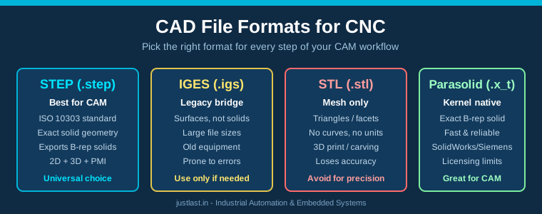
CNC machines cannot directly read 3D model files (STL, STEP, or IGES). They require G-code files (.nc or .tap format) that contain the machine coordinates, feed rates, spindle speeds, and tool change commands. The process of converting a 3D model into G-code is called CAM (Computer-Aided Manufacturing).
2. The Complete CAD/CAM Workflow
The workflow to generate G-code from 3D models consists of five sequential steps:
Design (CAD) → CAM Setup → Post-Processing → G-Code Generation → CNC Machining
Each step is critical. Skipping verification (Step 4) is the most common cause of crashes, broken tools, and scrapped material when beginners start CNC machining.
3. Step 1: Design Your 3D Model
Start by creating or importing a 3D model in your preferred CAD software. The most common tools for Indian CNC users include:
- Fusion 360: All-in-one CAD/CAM with excellent CNC features. Best for beginners due to integrated workflow.
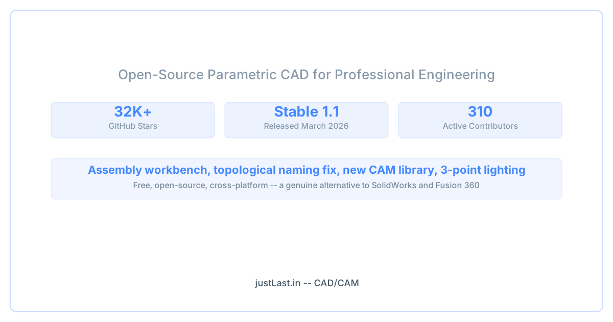
- FreeCAD: Free and open-source. The Path Workbench provides basic CAM functionality. Steeper learning curve.
- SolidWorks: Professional-grade CAD. Requires separate CAM add-on for G-code generation.
- Autodesk Inventor: Popular in Indian manufacturing. Also requires HSM CAM add-on.
When designing for CNC, keep these principles in mind:
- Use internal radii (fillet) at least 1.5x the tool diameter for internal corners
- Avoid sharp internal vertical corners — end mills cut round corners
- Design with the tool approach in mind — plan how the cutter will reach each feature
- Include stock allowance — the raw material is larger than the final part
4. Step 2: Set Up CAM Toolpaths
CAM setup is where you tell the software how to machine your part. This involves:
Define Stock: Set the raw material dimensions. For example, if your part is 50x50x20mm, the stock might be 60x60x25mm.
Select Tools: Choose end mills, ball mills, and drills from your tool library. Define tool diameter, flute length, and material (HSS vs carbide).
Set Machining Strategy: For each feature of your part, select an appropriate strategy:
- Adaptive Clearing — Roughing passes that clear material quickly
- Parallel Finishing — Smooth surface finish passes
- Contour — Following the part outline
- Pocket — Clearing enclosed areas
- Drilling — Hole-making cycles
Define Feeds and Speeds: Set spindle RPM, feed rate (mm/min), plunge rate, and stepover based on material and tool. For aluminum with a 6mm carbide end mill: RPM 12,000, feed 800 mm/min, stepover 3mm.
5. Step 3: Configure the Post-Processor
The post-processor is the bridge between your CAM software and your specific CNC machine. It translates generic toolpath data into the exact G-code dialect that your machine controller understands.
Each CNC controller uses a slightly different G-code variant. Common ones in India include:
- GRBL: Used on Arduino-based CNC machines (3018, 6040 routers). Simple, well-documented.
- Mach3/Mach4: Popular on desktop CNC mills and routers. Supports macros and probing.
- LinuxCNC: Open-source controller used on industrial retrofits. Very flexible.
- Fanuc Oi: Industrial standard for VMC machines in Indian workshops.
- Siemens 808D/828D: Common on imported Chinese VMCs and lathes.
In Fusion 360, select your post-processor from the library (500+ configurations included). For a common setup like a GRBL-based CNC 3018 router, use the “grbl.cps” post-processor.
6. Step 4: Generate and Verify G-Code
After post-processing, you’ll have an .nc file containing hundreds or thousands of lines of G-code. Never run G-code on your machine without verification first.
Use these free verification tools:
- NCViewer (ncviewer.com): Web-based G-code simulator. Drag and drop your .nc file to see the toolpath.
- CAMotics: Open-source 3-axis G-code simulator. Shows material removal in real time.
- CNCjs: Web-based controller with built-in visualization for GRBL machines.
- Fusion 360 Simulation: Built-in toolpath simulation with material removal and collision detection.
Check for these common issues during verification: tool colliding with clamps or fixtures, rapid moves that plunge into the material, excessive air cutting (wasted time), and missing features or incomplete toolpaths.
7. Step 5: CNC Machine Setup and Cutting
Transfer the verified G-code file to your CNC machine via SD card, USB, or direct connection (serial over USB for GRBL). Before starting the cut:
- Secure the stock material firmly using clamps, double-sided tape, or a vice
- Set the workpiece zero (WCS offset) using a touch probe or edge finder
- Set tool length offsets for each tool in the program
- Perform a dry run with Z-axis raised 5mm above the stock to verify all movements
- Start with reduced feed rates (50%) for the first cut
8. Common Issues and Troubleshooting
Tool breaks on first pass: Feed rate too high or depth of cut too aggressive. Reduce stepdown by 50% and check that spindle speed is appropriate for the tool diameter and material.
Surface finish is rough: Use a finishing pass with 0.2-0.5mm radial stepover. Check for tool runout — if the end mill has more than 0.05mm runout, replace the collet or tool holder.
Part dimensions are wrong: Calibrate your machine steps/mm. Run a test square and measure actual vs commanded size. Adjust axis steps per mm in GRBL ($100, $101, $102).
G-code has errors on machine: Your post-processor might be generating code for a different controller. Verify that the post-processor matches your machine (GRBL vs Mach3 vs Fanuc).
Frequently Asked Questions
What is the easiest way to generate G-code from 3D models?
Fusion 360 is the easiest option for beginners because it combines CAD and CAM in one interface. Design your model, switch to the Manufacture workspace, set up toolpaths, and click Post Process to generate G-code in minutes.
Can I generate G-code from STL files?
Yes. Most CAM software can import STL files. However, STL files are triangle meshes without parametric features, so you’ll have less control over machining strategies compared to STEP or Fusion 360 native files.
Do I need to know G-code to use CAM software?
No. Modern CAM software generates G-code automatically based on your toolpath selections and post-processor configuration. However, understanding basic G-code (G00, G01, G02, G90, G91) helps with troubleshooting.
What free software can generate G-code?
FreeCAD with the Path Workbench, Estlcam (free for 500 lines), and Fusion 360 for personal use (free for hobbyists) are the best free options for generating G-code from 3D models.
How do I know if my G-code is correct before machining?
Use a G-code simulator like NCViewer or CAMotics to visualize the toolpath. Check for rapid moves into the material, missing features, and excessive Z-axis movements. Always perform a dry run with the spindle off and Z raised.
Related Reading
- GRBL CNC Setup Guide: From Arduino to Your First Engraving Project
- CNC Machine Calibration: Step-by-Step Guide for Precision Machining
- Fusion 360 vs SolidWorks for CNC Machining: Complete Comparison Guide
Sources
- Autodesk Fusion 360 CAM Documentation
- NCViewer — G-Code Simulator
- CAMotics — Open Source G-Code Simulator
- GRBL — Open Source CNC Controller
- LinuxCNC Documentation
Disclosure: This post contains affiliate links. As an Amazon Associate, we earn from qualifying purchases.