Key Takeaway: CNC lathe programming centres on two axes, X (diameter) and Z (length), and a handful of G-codes – G00, G01, G71 roughing, G70 finishing, G76 threading and G96/G97 spindle modes – that turn stock into finished turned parts reliably and repeatedly.
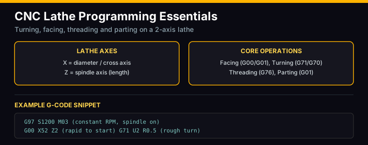
Table of Contents
1. CNC Lathe Basics: Axes and Machine Setup
A CNC lathe (turning centre) rotates the workpiece while a single-point cutting tool removes material. Unlike a mill, where the tool rotates, on a lathe the work spins and the tool moves along two axes: X and Z. This is the mental model that separates CNC lathe programming from milling – you are always thinking about diameters and lengths, not widths and heights.
The Z axis runs parallel to the spindle, along the length of the part. Z zero is usually the front face of the finished part. The X axis runs perpendicular to the spindle and is programmed in diameter values – an X coordinate of 50 means a 50 mm diameter, not a 50 mm radius. This diameter programming convention is a frequent source of beginner errors, so memorise it early.
Setup involves mounting a chuck or collet, touching off the tool against the faced stock to establish the work offset, and setting the tool turret offsets for each insert. Most lathe programs are written with the tool moving in negative Z (toward the chuck) for turning and positive Z (away) for facing and cut-off.
2. G-code Fundamentals for Turning Centres
The G-codes used in CNC lathe programming form a small, powerful set. The motion words are the same as milling – G00 for rapid positioning and G01 for linear feed – but the modal groups differ in important ways.
G96 constant surface speed: The default for turning. You program a surface speed in m/min (e.g., G96 S180), and the control automatically raises spindle RPM as the tool moves toward the centre so the cutting edge always runs at the same speed. This protects tool life and finish.
G97 constant RPM: Used for threading and when a fixed spindle speed is required (e.g., G97 S1200 M03). Threading must run at constant RPM so the spindle and lead screw stay synchronised.
G99 feed per revolution: The default feed mode on lathes – feed is programmed in mm/rev, not mm/min. This is the biggest difference from milling and keeps the chip load constant regardless of spindle speed.
G50 maximum spindle speed limit: Used with G96 to cap the RPM (G50 S3000) so the chuck and workpiece stay safe as the tool approaches centre.
G28/G30 home return: Returns the turret to a safe position, typically called before a tool change.
3. Facing, Roughing and Finishing
Facing is the first operation: it squares off the raw stock and establishes the Z zero reference face. A typical facing move is G00 X52 Z2, then G01 Z0 F0.1 to touch the face, followed by G01 X-1.6 F0.15 to cut across the face past centre. The small negative X overshoot ensures the centre is cleaned.
Roughing removes the bulk of the material. Rather than writing hundreds of lines of G01 moves, you use the G71 roughing cycle, which takes a profile description and machines it in a series of depth-of-cut passes automatically:
G71 U(depth) R(retract); then G71 P(profile start block) Q(profile end block) U(finish X allowance) W(finish Z allowance) F(feed). The control steps the tool across the profile, leaving a small stock allowance for finishing.
Finishing uses G70 with the same P and Q block numbers, cutting the final profile at finishing feed to hit the part dimensions and surface finish. This G71/G70 pairing is the backbone of almost every CNC lathe program and dramatically shortens programming time.
4. Threading with G76
Threading is where lathes do something mills cannot. The G76 threading cycle cuts a thread over multiple spring passes using a single-point insert ground to the thread form:
G76 P(m) Q(minimum depth) R(compound depth); then G76 X(thread minor diameter) Z(end of thread) P(thread depth, radius) Q(first pass depth) F(lead in mm/rev).
The P word in the first block encodes finish passes, chamfer amount and thread angle (a typical value is P021060: 2 finish passes, 0.1 mm chamfer, 60-degree thread). The lead F must equal the thread pitch – for an M12 x 1.75 thread, F1.75.
Threading demands G97 constant RPM, a spindle speed roughly one-quarter of turning speed, and radial infeed that decreases each pass so the cutting force stays manageable. The machiningdoctor resource linked in Sources explains the infeed distribution in detail. A lathe with a poorly maintained lead screw or spindle encoder will produce ragged threads – quality threading is a good test of machine health.
5. Grooving and Parting
Grooving cuts an internal or external recess for snap rings, O-rings or chip clearance. A groove is programmed with G01 moves using a grooving insert – plunge to depth at a low feed, dwell briefly, then retract. Deep grooves should be cleared in several steps, each slightly wider than the insert, to avoid side-loading the tool.
Parting (cut-off) separates the finished part from the stock. It uses a narrow parting insert fed radially at low feed with plenty of coolant. The classic failure is chatter or insert breakage caused by too high a feed, too deep a cut, or worn guides. Part-off feed is typically 0.05-0.12 mm/rev depending on material, and the spindle should slow as the tool approaches the centre (G96 handles this automatically).
6. Complete Lathe Program Example
Here is a compact example that faces, roughs, finishes and threads a short M12 stud from 25 mm diameter steel bar:
N10 G21 G99; (metric, feed per rev)
N20 T0101; (rough turning tool)
N30 G96 S180 G50 S2500 M03; (surface speed, RPM cap, spindle on)
N40 G00 X26 Z2; (rapid to start)
N50 G71 U2 R0.5; (rough cycle, 2 mm depth)
N60 G71 P70 Q110 U0.5 W0.1 F0.25;
N70 G00 X0; (profile: face centre)
N80 G01 Z0 F0.12;
N90 G01 X12 Z-1 F0.15; (chamfer)
N100 G01 Z-30;
N110 G01 X25;
N120 G70 P70 Q110; (finish profile)
N130 G28 U0 W0; (home)
N140 T0303; (threading tool)
N150 G97 S1000 M03; (constant RPM for threading)
N160 G00 X13 Z5;
N170 G76 P021060 Q0.1 R0.05; (thread cycle)
N180 G76 X10.1 Z-24 P1100 Q250 F1.75; (M12 x 1.75 thread)
N190 G28 U0 W0; M30; (home, end)
This single program produces a finished, threaded part – the compactness is exactly why CNC lathe programming is so productive once the cycles are mastered.
7. Feeds, Speeds and Depth of Cut for Turning
Turning parameters follow the same logic as milling but are referenced to the workpiece diameter. Cutting speed for turning is typically 120-250 m/min for aluminium, 80-150 m/min for mild steel and 60-100 m/min for stainless with carbide inserts. Feed for rough turning is 0.2-0.4 mm/rev; finishing runs 0.05-0.15 mm/rev.
Depth of cut for roughing is usually 2-5 mm per side on rigid machines, dropping to 0.2-0.5 mm for finishing. The full formulas for RPM and feed are covered in our feeds and speeds guide – the same maths applies, just referenced to the turned diameter instead of the tool diameter.
Long slender parts are the classic lathe problem: cutting force deflects the work, producing taper and chatter. Support the part with a tailstock centre, reduce depth of cut, and feed toward the chuck rather than away from it. If you are designing your own lathe conversion or retrofitting, understanding the motion-control side matters too – the stepper vs servo selection guide and smart CAM strategies are good companions.
Frequently Asked Questions
What G-codes are used in CNC lathe programming?
The core set is G00 (rapid), G01 (feed), G96 (constant surface speed), G97 (constant RPM), G99 (feed per rev), G71/G70 (rough/finish), G76 (threading) and G28 (home return). Cycles like G71 collapse dozens of moves into a few lines.
Why is the X axis programmed in diameter on a lathe?
Lathe controls use diameter programming as the default so the programmed X value equals the part diameter. A tool at X40 machines a 40 mm diameter. Radius programming exists but is rarely used and a common source of errors.
What is the difference between G96 and G97?
G96 keeps a constant surface speed in m/min, varying the spindle RPM as the tool moves across the face. G97 fixes the spindle at a constant RPM and is mandatory for threading, where spindle and lead screw must stay synchronised.
How do I thread on a CNC lathe?
Use the G76 cycle at constant RPM (G97). Program the minor diameter, thread depth, first-pass depth and pitch (lead) in F. The control takes multiple spring passes automatically to form the thread.
Do I need a CAM program for a lathe?
For simple turned parts, manual G-code is fast and effective. For complex profiles with multiple tools and radii, CAM (e.g., Fusion 360) generates the cycles and avoids manual arithmetic – our CAM toolpath workflow guide shows the process.
Related Reading
- Feeds and Speeds for CNC Machining
- Fusion 360 CAM Guide: Complete CNC Toolpath Workflow
- How to Generate G-code from 3D Models
- CNC Machining Time Reduction: Smart CAM Strategies
- Stepper vs Servo Motors for CNC
Sources
- Sandvik Coromant: Turning Knowledge Base
- CNC Cookbook: CNC Lathe G-Code Tutorial
- MachiningDoctor: G76 Threading Cycle
- Haas: CNC Lathe Programming Resources
- Carbide Depot: Turning Formulas
Disclosure: This post may contain affiliate links. If you purchase through these links, we may earn a commission at no extra cost to you. Recommendations are based on engineering merit, not affiliate revenue.