Key Takeaway: The I2C protocol is the most widely used two-wire serial communication standard in embedded systems, connecting microcontrollers like Arduino and STM32 to sensors, displays, and peripherals using just two pins — SDA (data) and SCL (clock). Understanding addressing, wiring, and pull-up resistors is essential for reliable communication.
Table of Contents
1. I2C Protocol Basics
I2C (Inter-Integrated Circuit), also written as I²C, was developed by Philips Semiconductor (now NXP) in 1982 as a simple two-wire bus for connecting peripheral chips to microcontrollers. The protocol uses two bidirectional open-drain lines: SDA (Serial Data) and SCL (Serial Clock), both pulled high with external resistors.
The I2C protocol operates in a master-slave architecture. The master (typically your microcontroller) generates the clock signal on SCL, initiates and terminates data transfers, and addresses specific slave devices. Slaves (sensors, ADCs, displays, EEPROMs) listen for their address on the bus and respond only when addressed.
Standard I2C bus speeds are 100 kHz (standard mode), 400 kHz (fast mode), 1 MHz (fast mode plus), and 3.4 MHz (high-speed mode). Most microcontrollers and sensors support standard mode and fast mode. STM32 MCUs commonly support all modes up to 1 MHz, while Arduino’s Wire library defaults to 100 kHz.
The bus protocol works like this: the master pulls SDA low while SCL is high (a START condition), sends the 7-bit slave address followed by a read/write bit, the slave acknowledges (ACK), data bytes are transferred with the clock, and the master ends with a STOP condition (SDA going high while SCL is high).
2. Wiring I2C Devices
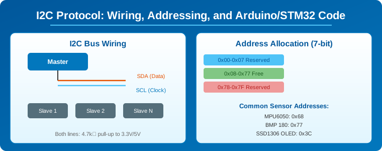
Wiring I2C is deceptively simple — connect all SDA pins together and all SCL pins together, add pull-up resistors, and connect power and ground. The entire bus runs on two wires regardless of how many devices are connected.
Pull-up resistors are critical. I2C uses open-drain signaling, meaning devices can only pull lines LOW. The pull-up resistors are what return the line to HIGH when no device is driving it. Without pull-ups, the bus will not work at all. With values that are too high (above 10 kΩ), the bus will work but signals will be slow and distorted at higher speeds. With values too low (below 1 kΩ), the drivers may not be able to pull the line low enough.
The standard value is 4.7 kΩ for 100 kHz operation at 5V. For 3.3V systems, 3.3 kΩ to 4.7 kΩ is typical. For 400 kHz operation, you may need 2.2 kΩ to 3.3 kΩ. Many breakout boards include on-board pull-ups, so check with a multimeter before adding extra resistors.
Bus capacitance limits the total number of devices and cable length. The maximum capacitance for standard mode is 400 pF, which limits the bus to about 1-2 meters of cable and roughly 8-16 devices (depending on each device’s pin capacitance). For longer runs, use an I2C buffer like the PCA9600.
3. I2C Addressing Explained
I2C uses 7-bit addressing, which theoretically supports 128 addresses (0x00 to 0x7F). However, 0x00-0x07 and 0x78-0x7F are reserved for special purposes, leaving 112 available addresses. Each slave device on the bus must have a unique address.
Many sensors and modules have a fixed address or an address that can be changed by one or two options. For example, the MPU6050 accelerometer/gyroscope has address 0x68 (or 0x69 if the AD0 pin is pulled high). The BMP180 barometric sensor uses 0x77. The common SSD1306 OLED display uses 0x3C (or 0x3D).
When two devices share the same address, they cannot coexist on the same I2C bus. Solutions include: using an I2C multiplexer (like the TCA9548A), changing the address via device pins if available, or using a second I2C peripheral on your microcontroller (many STM32 chips have multiple I2C peripherals — I2C1, I2C2, I2C3).
4. I2C on Arduino — Wire Library
Arduino’s Wire library provides a simple API for I2C communication. On Arduino Uno, SDA is A4 and SCL is A5. On Arduino Mega, SDA is 20 and SCL is 21. On newer boards like the Arduino Nano Every and Nano 33 IoT, the pin mapping is different — always check the datasheet.
Here is a complete Arduino master writer example that writes to a slave device at address 0x68:
#include <Wire.h>

void setup() {
  Wire.begin();                // Join I2C bus as master
  Serial.begin(115200);
}

void loop() {
  Wire.beginTransmission(0x68); // Slave address
  Wire.write(0x3B);             // Register to write to
  Wire.write(0x00);             // Data byte
  Wire.endTransmission();       // Send and stop

  delay(100);
}
For reading from a slave, the pattern uses a repeated start (requestFrom): first write the register address, then request bytes:
#include <Wire.h>

void setup() {
  Wire.begin();
  Serial.begin(115200);
}

void loop() {
  Wire.beginTransmission(0x68);
  Wire.write(0x3B);              // Register to read
  Wire.endTransmission(false);   // false = repeated start

  Wire.requestFrom(0x68, 2);     // Request 2 bytes
  while (Wire.available()) {
    byte data = Wire.read();
    Serial.println(data, HEX);
  }
  delay(500);
}
5. I2C on STM32 — HAL Library
STM32 microcontrollers have robust I2C peripherals with hardware support for all bus speeds up to 1 MHz. The STM32 HAL (Hardware Abstraction Layer) provides several functions for I2C communication: blocking (HAL_I2C_Master_Transmit/Receive), interrupt-based (HAL_I2C_Master_Transmit_IT/Receive_IT), and DMA-based (HAL_I2C_Master_Transmit_DMA/Receive_DMA).
Here is an STM32 I2C master transmit example using HAL (assuming I2C1 is initialized with HAL_I2C_Init):
#include "stm32f1xx_hal.h"
extern I2C_HandleTypeDef hi2c1;
void I2C_WriteRegister(uint8_t dev_addr, uint8_t reg, uint8_t data) {
uint8_t buf[2] = {reg, data};
HAL_I2C_Master_Transmit(&hi2c1, dev_addr << 1, buf, 2, HAL_MAX_DELAY);
}
uint8_t I2C_ReadRegister(uint8_t dev_addr, uint8_t reg) {
uint8_t data;
HAL_I2C_Master_Transmit(&hi2c1, dev_addr << 1, ®, 1, HAL_MAX_DELAY);
HAL_I2C_Master_Receive(&hi2c1, dev_addr << 1, &data, 1, HAL_MAX_DELAY);
return data;
}
Note that STM32 HAL uses 8-bit addresses (address shifted left by 1 bit), so a device with 7-bit address 0x68 is passed as 0xD0. This is a common source of confusion when porting Arduino code to STM32. The HAL_I2C_Master_Transmit expects the 8-bit address with the R/W bit as the LSB, while Arduino Wire.beginTransmission uses the raw 7-bit address.
For interrupt-based operation, which is preferred in non-blocking applications:
uint8_t rx_buffer[16];
volatile uint8_t rx_complete = 0;
void Start_I2C_Read(uint8_t dev_addr, uint8_t reg, uint8_t len) {
HAL_I2C_Master_Transmit_IT(&hi2c1, dev_addr << 1, ®, 1);
// Wait for transmit complete, then:
HAL_I2C_Master_Receive_IT(&hi2c1, dev_addr << 1, rx_buffer, len);
}
void HAL_I2C_MasterRxCpltCallback(I2C_HandleTypeDef *hi2c) {
if (hi2c->Instance == I2C1) {
rx_complete = 1;
}
}
6. Troubleshooting I2C Issues
I2C problems are common and usually come from three sources. First, missing or incorrect pull-up resistors. Use an oscilloscope to check if SDA and SCL lines have clean transitions. A slow rise time indicates excessive bus capacitance — reduce the pull-up resistor value or lower the bus speed.
Second, address conflicts. Use an I2C scanner sketch (available in Arduino examples) to enumerate all devices on the bus. If a device doesn’t appear, verify its address in the datasheet (some addresses are 7-bit, some 8-bit) and check if address pins need to be tied high or low.
Third, clock stretching issues. Some slaves hold SCL low to indicate they need more time (clock stretching). Some Arduino Wire library versions have limited clock stretching support. The solution is to use a lower bus speed or to add a small delay between transactions.
An I2C bus analyzer or a cheap logic analyzer (like the Saleae clone or USB logic analyzer) is the best diagnostic tool. It captures the actual SDA/SCL waveforms and decodes START/STOP conditions, addresses, ACK/NACK, and data bytes.
Frequently Asked Questions
What is the maximum cable length for I2C?
Standard I2C is designed for on-board communication, not cables. For short cables (under 1 meter) at 100 kHz, it usually works. For longer distances, use an I2C buffer/extender like the PCA9600 or switch to RS-485 or CAN bus for multi-drop communication over longer runs.
Can I use I2C with different voltage devices (3.3V and 5V)?
Yes, but you need a voltage-level translator or you can use a single pull-up voltage. Many I2C devices are 5V tolerant on their I2C pins. If mixing 3.3V and 5V devices, use a level shifter module (which uses a MOSFET per channel) or ensure all devices can tolerate the pull-up voltage.
How do I find a device’s I2C address?
Upload the Wire library’s i2c_scanner example sketch to your Arduino. It will scan addresses 1-127 and print every device that responds with an ACK. For STM32, the HAL_I2C_IsDeviceReady function tests a specific address, and you can loop through addresses 0x00-0x7F.
What is clock stretching in I2C?
Clock stretching is when a slave device holds SCL low after the master releases it, signaling that it needs more time to prepare data. The master must wait until SCL goes high before continuing. Most modern I2C peripherals handle this automatically, but some software bit-bang implementations may fail.
Is I2C faster than SPI?
No. SPI (Serial Peripheral Interface) is generally faster because it runs at higher clock rates (up to 80 MHz) and is full-duplex. I2C maxes at 3.4 MHz (high-speed mode) and is half-duplex. However, I2C uses only 2 wires regardless of the number of devices, while SPI requires a separate chip select line per device.
Related Reading
- STM32 Sensor Data Acquisition for Industrial IoT
- RISC-V Microcontrollers Revolutionizing Embedded Systems
- Industrial IoT Sensor Networks: Wireless Protocols, Edge Processing
Sources
- NXP — I2C Bus Specification and User Manual (UM10204)
- Arduino — Wire Library Reference
- STMicroelectronics — STM32F103 I2C Peripheral Datasheet
- TI — I2C Bus Pull-Up Resistor Calculation
Disclosure: This post contains affiliate links to development boards and tools on Amazon. We may earn a commission if you purchase through these links.