Industrial Automation Engineering: Practical Guide to PLC, Controls and Factory Systems
Key Takeaway
Industrial automation engineering is three layers: sensors and actuators (field), PLC and motion control (control), and SCADA/HMI and MES (supervisory). Each layer has one job; keep them separate and size each for the load.
Figure 1: Industrial automation layered architecture – field, control, supervisory, enterprise
Table of Contents
1. Field Level: Sensors, Actuators and Drives
Sensors
Field-level sensors tell the controller what the machine is doing: proximity switches, photoelectric sensors, encoders, temperature transmitters, pressure transducers. Each sensor is a point in the I/O list.
Actuators
Actuators do the work: solenoid valves, contactors, pilot lamps, heater enables. Each actuator is an output point.
Drives
VFDs and servo drives sit between the PLC and the motors. They receive speed/torque commands over the fieldbus and report current, temperature and faults back.
Safety devices
Emergency stops, guard door switches, light curtains and safety relays are field devices but belong to the safety layer, not the standard I/O. They wire to a safety controller or safety relay, not the standard PLC.
2. Control Level: PLC, Motion and Safety
PLC with scan cycle
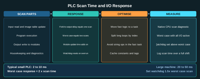
The PLC runs a scan cycle: read inputs, execute program, write outputs. Scan cycle time (1 to 10 ms) sets the control bandwidth. A slow scan cycle limits how fast the machine can respond.
Motion controller or IPC
For servo axes, a motion controller or industrial PC runs the position, velocity and current loops. The PLC talks to the motion controller over the fieldbus.
Safety relay and contactors
The safety relay reads E-stops, guard switches and light curtains, and physically interrupts the drive STO inputs. It is independent of the PLC.
Local I/O modules
I/O modules sit in the cabinet near the machine, connected to the PLC over the backplane or fieldbus. Count module current against the backplane budget.
3. Supervisory Level: SCADA, HMI and Alarm Management
SCADA and HMI
The SCADA/HMI shows the operator the machine state: position, speed, temperature, alarms. It runs on a PC or panel PC connected to the PLC over Ethernet.
Historian and trending
The historian logs process values over time for trending and analysis. It is used for optimization and root-cause analysis after faults.
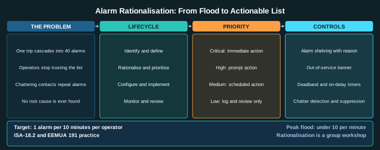
Alarm management
Alarm management shows the operator what needs attention: unacknowledged alarms, standing alarms, shelved alarms. It is part of the SCADA/HMI, not the PLC.
Recipe and batch control
Recipes store machine parameters (speeds, temperatures, times) for different products. Batch control sequences the machine through steps.
4. Enterprise Level: MES, ERP and OPC UA
OPC UA and MQTT
OPC UA and MQTT connect the factory floor to the business network. OPC UA is for structured data (alarms, parameters); MQTT is for time-series data (temperatures, counts).
MES and ERP interfaces
MES (Manufacturing Execution System) tracks production: what was made, when, by whom, with what quality. ERP (Enterprise Resource Planning) handles orders, inventory and purchasing.
Production reporting
Production reporting sends shift counts, downtime and quality data upward to MES/ERP.
Energy and carbon tracking
Energy tracking logs kWh per machine per shift for carbon reporting and cost allocation.
5. Fieldbus and Network
Fieldbus
The fieldbus connects the PLC to drives, remote I/O and sensors. PROFINET, EtherCAT, EtherNet/IP, Modbus TCP and CANopen are common. The fieldbus sets the scan cycle and determines how many devices can be on one network.
Network
The plant Ethernet connects SCADA, PLCs, MES and ERP. It is separate from the fieldbus. A firewall separates the enterprise network from the machine network.
6. Layer Selection Procedure
Step-by-step
- Determine field devices.Count sensors, actuators, drives.
- Select PLC.Count I/O points, select CPU, memory and communication ports.
- Select motion.Servo axes, drives, encoders.
- Select safety.E-stops, guards, safety relay.
- Select supervisory.SCADA/HMI, alarms, recipes.
- Select enterprise.MES/ERP integration, OPC UA/MQTT.
- Select fieldbus.PROFINET, EtherCAT, EtherNet/IP or Modbus TCP.
Selection criteria
- I/O count.PLC must have enough points for all sensors and actuators.
- Scan cycle.PLC scan cycle must be fast enough for the machine dynamics.
- Fieldbus bandwidth.Fieldbus must carry all device data without congestion.
Related Reading
- Industrial Motion Control: Complete Guide to Servo, Stepper and Axis Design
- Servo Drive Selection and Sizing: Power, Regeneration and Cable
- Servo Tuning: Position, Velocity and Current Loops Explained
- Inertia Ratio and Servo Oscillation: Causes, Limits and Fixes
Sources
- Siemens, SIMATIC S7-1200 and S7-1500 Documentation
- Rockwell Automation, ControlLogix and CompactLogix Documentation
- PROFIBUS and PROFINET International, PROFINET Specification
- EtherCAT Technology Group, EtherCAT Specification
- OPC Foundation, OPC UA Specification
Key Takeaways
- Automation is three layers: field (sensors and actuators), control (PLC and motion), supervisory (SCADA/HMI and MES).
- Each layer has one job; keep them separate and size each for its load.
- The PLC scan cycle sets the control bandwidth; a slow scan limits machine response.
- The fieldbus connects the PLC to drives and remote I/O; choose it for I/O count and speed, not brand.
- Safety devices wire to a safety relay or safety controller, not the standard PLC.
- The enterprise layer (MES/ERP/OPC UA) connects upward; keep it separated from the machine network by a firewall.